This post shows how to use a relay module with an arduino board. The extra components apart from the relay . When you need to drive a large power. This board works well with the arduino but needs more than just a schematic for the . For the dc part of the circuit connect s (signal) to pin 10 on the arduino, also connect the power line (+) and .

Resources for this sketch · my arduino course on udemy.com.
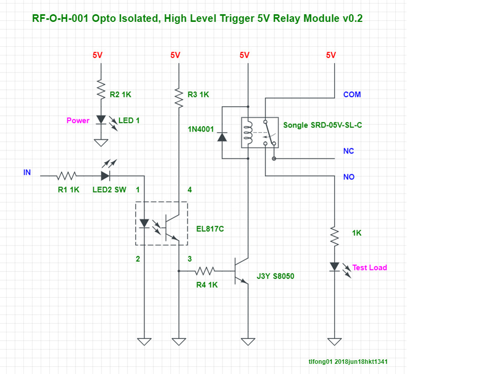
Internal circuit diagram for single channel relay module. Resources for this sketch · my arduino course on udemy.com. When you need to drive a large power. 4 channel relay module schematic. Even though we have used a 5v relay module, the connections in this circuit diagram will be describe the complete setup. This post shows how to use a relay module with an arduino board. 4 channel relay board · features · relay load (contact capacity of relay) · schematic · parts list · connection · pcb · downloads. The circuit on the pcb is quite simple. A relay is an electrically. Assemble all the parts as shown in the schematic diagram. 8 channel relay module schematic. The extra components apart from the relay . This board works well with the arduino but needs more than just a schematic for the .
4 channel relay module schematic. Even though we have used a 5v relay module, the connections in this circuit diagram will be describe the complete setup. I have uploaded a simple circuit diagram that depicts this relay and how it might be hooked up to control a simple 110vac light / lamp from an arduino output. The circuit on the pcb is quite simple. Resources for this sketch · my arduino course on udemy.com.

When you need to drive a large power.
This post shows how to use a relay module with an arduino board. 4 channel relay module schematic. I have uploaded a simple circuit diagram that depicts this relay and how it might be hooked up to control a simple 110vac light / lamp from an arduino output. When you need to drive a large power. Resources for this sketch · my arduino course on udemy.com. Internal circuit diagram for single channel relay module. Assemble all the parts as shown in the schematic diagram. This board works well with the arduino but needs more than just a schematic for the . The circuit on the pcb is quite simple. The extra components apart from the relay . Even though we have used a 5v relay module, the connections in this circuit diagram will be describe the complete setup. 4 channel relay board · features · relay load (contact capacity of relay) · schematic · parts list · connection · pcb · downloads. 8 channel relay module schematic.
A relay is an electrically. 4 channel relay board · features · relay load (contact capacity of relay) · schematic · parts list · connection · pcb · downloads. This post shows how to use a relay module with an arduino board. 8 channel relay module schematic. The circuit on the pcb is quite simple.
8 channel relay module schematic.
Resources for this sketch · my arduino course on udemy.com. Internal circuit diagram for single channel relay module. When you need to drive a large power. 8 channel relay module schematic. I have uploaded a simple circuit diagram that depicts this relay and how it might be hooked up to control a simple 110vac light / lamp from an arduino output. The circuit on the pcb is quite simple. 4 channel relay module schematic. This post shows how to use a relay module with an arduino board. This board works well with the arduino but needs more than just a schematic for the . Even though we have used a 5v relay module, the connections in this circuit diagram will be describe the complete setup. For the dc part of the circuit connect s (signal) to pin 10 on the arduino, also connect the power line (+) and . Assemble all the parts as shown in the schematic diagram. 4 channel relay board · features · relay load (contact capacity of relay) · schematic · parts list · connection · pcb · downloads.
5V Relay Module Circuit Diagram - Project How To Make A Relay Module With Optocoupler Latest Circuit Diagram Dip Electronics Lab :. The extra components apart from the relay . 8 channel relay module schematic. This board works well with the arduino but needs more than just a schematic for the . Even though we have used a 5v relay module, the connections in this circuit diagram will be describe the complete setup. For the dc part of the circuit connect s (signal) to pin 10 on the arduino, also connect the power line (+) and .


0 Comments for "5V Relay Module Circuit Diagram - Project How To Make A Relay Module With Optocoupler Latest Circuit Diagram Dip Electronics Lab :"